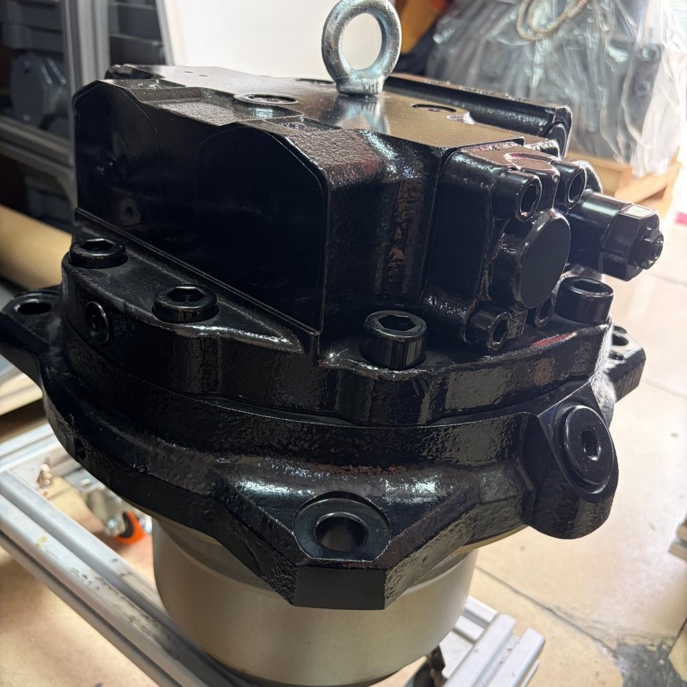
A sudden travel drive failure on a 30-ton excavator halts production across an entire earthmoving site or mining bench. When an excavator loses tracking force, stalls on inclines, or locks up a single track, the underlying cause almost always traces back to the excavator final drive. Operating at hydraulic operating pressures up to 350 bar (5,076 psi) and generating massive output torque, final drive assemblies endure continuous mechanical stress in abrasive field environments.
For equipment directors, fleet maintenance engineers, and procurement managers, managing final drive performance requires balancing operational uptime against Total Cost of Ownership (TCO). Replacing a failed unit through traditional main dealership channels often entails severe lead-time delays and elevated procurement costs.
This technical guide breaks down the internal mechanics of excavator final drives, outlines a systematic diagnostic framework for common failure symptoms, compares OEM versus quality aftermarket replacement economics, and details a 5-point procurement checklist to protect your fleet investment.
What Is an Excavator Final Drive? Mechanical & Hydraulic Principles
The final drive is the terminal power transmission unit positioned on each side of a crawler excavator’s undercarriage. Mounted directly to the track frame, its primary role is to transform high-pressure hydraulic fluid flow from the main hydraulic pump into low-speed, high-torque rotational movement that turns the track sprocket.
A complete final drive unit integrates two distinct mechanical modules operating within a single housing assembly:
Main Hydraulic Pump → High-Pressure Oil (350 bar) → Axial Piston Travel Motor → Rotary Motion → Planetary Reduction Gearbox → High Torque (40:1) → Sprocket & Track Drive
1. The Hydraulic Travel Motor
The rear section of the assembly houses a variable-displacement axial piston hydraulic motor. High-pressure hydraulic fluid enters the motor through control ports, pushing internal pistons against an angled swashplate to convert fluid pressure into shaft rotation.
Most modern excavators utilize dual-displacement travel motors. When the operator triggers high-speed travel mode, a pilot-operated displacement control valve flattens the swashplate angle. This action decreases motor displacement per revolution, increasing track rotation speed while proportionally lowering output torque for fast transit across smooth terrain.
The motor housing also contains a spring-applied, hydraulically released mechanical parking brake disc assembly. When travel pilot pressure drops to zero, heavy coil springs compress friction discs against steel plates, locking the drive shaft to prevent machine roll-slip on inclines.
2. The Planetary Reduction Gearbox
The front section consists of a multi-stage (typically 2-stage or 3-stage) planetary gear reduction system. Because hydraulic motors rotate at relatively high speeds (1,000–2,500 RPM) with modest shaft torque, the planetary gearbox reduces input speed by ratios up to 40:1 while multiplying torque proportionally.
Inside the gearbox:
- The motor output shaft connects to the sun gear of the first reduction stage.
- The sun gear drives three or four planet gears held inside a rotating planet carrier.
- The planet gears mesh simultaneously with an outer stationary or rotating ring gear (annulus).
- Power transfers sequentially through secondary and tertiary planetary stages to drive the outer hub shell and track sprocket.
3. Duo-Cone Floating Seals & Fluid Segregation
Because final drives operate submerged in mud, water, and abrasive rock dust, maintaining fluid isolation is essential. The joint between the rotating sprocket hub and the stationary motor housing is sealed by heavy-duty Duo-Cone floating metal face seals. Two precision-lapped alloy steel seal rings, energized by rubber toric rings, maintain a continuous oil-tight seal even under heavy frame deflection.
Key Takeaway: The final drive maintains two completely separate fluid chambers: hydraulic oil (ISO VG 46/68) operating under high pressure in the travel motor, and extreme-pressure gear lubricant (EP ISO VG 220 / SAE 80W-90) operating at atmospheric pressure inside the planetary gear casing. Cross-contamination between these chambers indicates critical internal seal failure.
5 Common Failure Symptoms & Diagnostic Troubleshooting Matrix
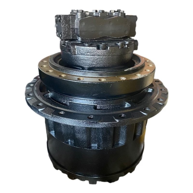
When an excavator displays travel abnormalities, early diagnosis prevents minor component wear from cascading into catastrophic housing lockup.
1. One-Sided Travel Weakness or Steering Drift
Symptom: The excavator tracks unevenly, pulling toward one side during straight travel, or fails to climb steep grades.
Root Causes:
- Internal Hydraulic Bypass: Worn cylinder block faces, scored piston shoes, or eroded swashplate surfaces allow high-pressure oil to slip directly into the motor case return without generating mechanical torque.
- Relief Valve Miscalibration: A sticking or misadjusted main travel relief valve vents pressure prematurely below specified operating thresholds (e.g., relieving at 240 bar instead of 350 bar).
- Control Valve Isolation: Faults in the main control valve spool or center swivel joint (rotary manifold) seals starve one motor of adequate fluid volume.
Pro Tip: To isolate whether travel weakness originates in the final drive motor or the main hydraulic system, perform a pressure swap test at the center swivel joint or inspect electrical control inputs. For fleet managers overseeing multi-system Hitachi machinery, integrating a structured diagnostic routine alongside a Hitachi excavator computer board troubleshooting guide ensures electronic pump control signals are verified before replacing mechanical components.
2. High Case-Drain Backpressure & Shaft Seal Blowout
Symptom: Hydraulic oil rapidly floods the planetary gearbox, or the motor shaft oil seal blows out, forcing fluid into the undercarriage frame.
Root Causes:
- Clogged Case Drain Filter: Every axial piston motor bleeds a small volume of hydraulic oil into its casing for internal lubrication and cooling. This oil returns to the hydraulic reservoir through a dedicated case drain line. If the case drain filter or line becomes restricted by debris or mechanical kinking, casing pressure spikes above 2–3 bar (30–45 psi).
- Motor Piston Shoe Scoring: Severe internal motor wear increases case drain bypass flow beyond the discharge capacity of the drain line, building excessive internal pressure.
⚠️ Warning: Never operate an excavator with a restricted or kinked case drain line. Case pressure exceeding 3 bar will instantly rupture the main motor shaft seal, forcing high-pressure hydraulic fluid into the gear oil chamber and destroying the planetary reduction gears within hours.
3. Metallic Grinding Noise & Planetary Tooth Spalling
Symptom: Heavy grinding, clicking, or clunking sounds emanating from the track hub during travel.
Root Causes:
- Low Gear Lubricant Level: Operating the planetary gearbox with insufficient EP gear oil causes extreme metallic friction, heating planetary pinions above 120°C (248°F).
- Surface Spalling & Fatigue: Continuous shock loading causes microscopic surface cracks on sun gear teeth, eventually shedding metal flakes into the lubricant. These hard particles circulate through planetary needle bearings, causing total gear train destruction.
4. Duo-Cone Seal Oil Leakage
Symptom: Dark gear oil leaking from behind the track sprocket onto the track chain rollers.
Root Causes:
- Packing Debris: Fine wire, tree roots, or packed mud wrap around the sprocket hub, pushing past the outer dirt guard and cutting the rubber toric rings.
- Face Lapping Failure: Abrasive silica dust penetrating the seal gap scores the mirror-polished metallic seal faces, destroying the oil film boundary.
Diagnostic Troubleshooting Matrix
| Observed Symptom | Primary Suspect Area | Field Diagnostic Step | Recommended Action |
|---|---|---|---|
| Track lacks pulling power; engine does not lug | Internal motor leakage or low relief pressure | Measure travel circuit pressure at motor inlet test port (Target: 320–350 bar) | Re-calibrate travel relief valve; if pressure holds but motor slips, replace rotating group or drive assembly |
| Excavator moves in low speed only; won’t shift to high speed | Displacement control valve or pilot signal failure | Verify 35–40 bar pilot pressure at the speed changeover port during joystick activation | Clean/replace displacement solenoid valve; check internal swashplate control piston |
| High pressure in motor casing; shaft seal leaking | Clogged case drain line or excessive piston bypass | Measure case drain flow rate in a container over 60 seconds at relief pressure | Flush case drain lines; replace clogged return filter; replace worn motor rotating group |
| Black oil leaking from sprocket hub | Damaged Duo-Cone floating seal or torn toric ring | Drain planetary gear oil; inspect for water or hydraulic fluid contamination | Remove sprocket, clean seal seat, and install new Duo-Cone floating seal assembly |
| Grinding sound; magnetic drain plug coated in metal chips | Planetary gear tooth pitting or bearing collapse | Remove gearbox end cover; inspect sun and planet gear tooth engagement | Flush gear casing; replace damaged planetary stage gears and needle bearings |
OEM vs. Quality Aftermarket Final Drives: Total Cost of Ownership (TCO) Analysis
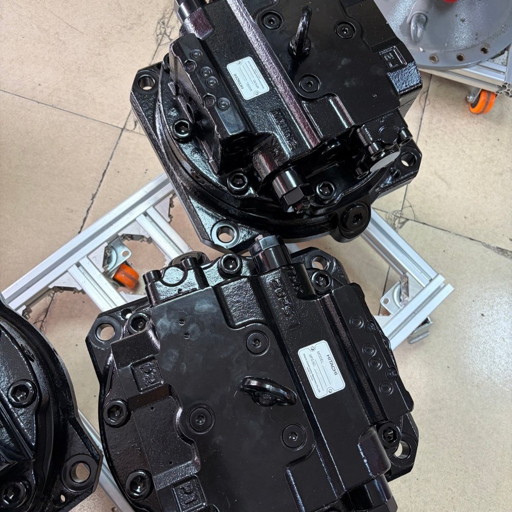
When a final drive suffers catastrophic failure, equipment directors face a critical procurement decision: purchase a new OEM assembly from an authorized main dealer, order a factory-direct aftermarket replacement, or rebuild the existing unit.
TOTAL COST OF OWNERSHIP (TCO) Direct Purchase Price + Shipping & Import Duty + Downtime Loss ($1,500/day)
1. Direct Purchase Price Comparison
OEM final drives carry heavy brand premiums and dealer markup. For 15- to 30-ton class excavators (such as Komatsu PC200, Hitachi ZX200, or CAT 320), replacement costs vary significantly across supply channels:
| Machine Class | OEM Dealer Price (USD) | Quality Aftermarket Price (USD) | Direct Capital Savings (%) |
|---|---|---|---|
| Compact (3–8 Ton) | $2,800 – $5,200 | $1,200 – $2,200 | 50% – 58% |
| Mid-Size (12–22 Ton) | $6,500 – $10,500 | $2,600 – $4,500 | 55% – 60% |
| Heavy-Duty (30–45 Ton) | $12,000 – $22,000+ | $5,500 – $9,800 | 50% – 55% |
2. Supply Chain Lead Time & Downtime Financial Impact
In heavy construction and mining operations, machine downtime costs extend far beyond shop repair labor. A stalled 30-ton excavator idling an active haul truck fleet can cost an operator $1,200 to $2,500 per day in lost production.
- OEM Dealer Delivery: Regional dealership networks frequently maintain minimal safety stock for complete travel assemblies, quoting lead times of 2 to 6 weeks for specialized factory orders. A 4-week lead time represents up to $35,000 in operational downtime losses.
- Factory-Direct Aftermarket Delivery: Specialized aftermarket manufacturers maintain dedicated inventory across high-demand OEM fitments, offering same-day dispatch and express international air freight delivery in 3 to 7 business days.
When evaluating supplier capabilities for sourcing heavy equipment replacement components, fleet managers must calculate lead-time risk alongside component price to determine true TCO.
3. Quality Standards & Engineering Metallurgy
A common concern regarding aftermarket final drives is mechanical durability under extreme peak loads. However, top-tier aftermarket manufacturers produce replacement assemblies engineered to match or exceed original factory specifications:
- Gear Steel Grade: High-strength 20CrMnTi or 8620 alloy steel subjected to multi-stage carburizing heat treatment, achieving surface hardness ratings of HRC 58–62 and core toughness to absorb heavy shock loads.
- Hydraulic Testing: 100% automated pressure and volumetric displacement bench testing prior to packaging, ensuring zero internal bypass at 350 bar test pressures.
- Dimensional Interchangeability: Machined on 5-axis CNC centers to maintain exact mounting bolt circle diameters (PCD), drive shaft splines, and port thread pitch matching original machinery specifications.
In addition to final travel drives, maintaining overall machine productivity requires equal attention to upper-structure rotation systems, such as specialized excavator swing gearbox assemblies, which operate under similar planetary reduction principles.
Step-by-Step Technical Selection Framework for Final Drive Replacement
To ensure a replacement final drive installs seamlessly without field modifications or performance mismatches, maintenance leads should follow this 4-step selection framework:
Step 1: Machine Profile Verification → Step 2: Mechanical Dimensions → Step 3: Hydraulic Matching → Step 4: Supply Verification
Step 1: Verify Machine Nameplate Details & Side Orientation
Always record the exact machine model, series prefix, and full serial number from the excavator frame nameplate. Manufacturers frequently modify internal motor displacement or sprocket bolt hole patterns between machine generations (e.g., Dash-3 vs. Dash-5 vs. Dash-6 series).
Additionally, verify whether the final drive requires specific left-hand (LH) or right-hand (RH) hose port orientation. While many symmetrical gearboxes permit 180° rotation, certain models feature asymmetric mounting flanges or directional brake release ports.
Step 2: Measure Key Mechanical Dimensions
If the original OEM part number tag is missing or illegible, verify physical dimensions using a digital caliper and thread gauge:
A: Sprocket Mounting Flange PCD & Holes B: Undercarriage Frame Pilot Diameter C: Frame Mounting Bolt Circle & Threads D: Overall Casing Depth & Frame Clearance
- Sprocket Pilot Diameter & Bolt Circle: Measure the outer flange diameter, number of sprocket mounting holes (e.g., 9, 12, or 16 bolt holes), and Pitch Circle Diameter (PCD).
- Frame Mounting Flange: Count frame attachment holes, thread pitch (e.g., M16 x 2.0 or M20 x 2.5), and main frame pilot register diameter.
- Sprocket Offset Distance: Measure distance from the frame mounting face to the sprocket centerline to maintain perfect track alignment with bottom rollers.
Step 3: Match Hydraulic Performance Parameters
Verify hydraulic motor specifications against main pump relief settings:
- Maximum Pressure Rating: Ensure the travel motor casing and valve block are rated for full system pressure (typically 320–350 bar).
- Flow Capacity: Match maximum allowable inlet flow (L/min) to prevent motor over-speeding.
- Main Port Thread Specification: Confirm port sizes (e.g., G3/4″, Code 62 flange, or ORFS fittings) to avoid requiring hydraulic hose adapters in tight frame quarters.
Browsing a structured Hongtengda excavator final drive catalog allows equipment buyers to cross-reference exact OEM part numbers and dimensional blueprints before ordering.
5-Point Supplier Verification Checklist for Equipment Buyers
Before issuing a purchase order for replacement final drives, procurement officers should evaluate aftermarket suppliers against five essential verification standards:
- 1. Certified Pre-Dispatch Hydraulic Bench Testing: Does the supplier perform 100% full-pressure, full-flow hydraulic bench testing on every unit before shipping, and can they supply dated test reports?
- 2. Metallurgical & Seal Specifications: Are planetary gears manufactured from carburized 20CrMnTi/8620 alloy steel (HRC 58–62), and are floating seals backed by high-temp HNBR or FKM (Viton) elastomeric rings?
- 3. 100% Fitment Guarantee & OEM Part Number Cross-Referencing: Does the supplier guarantee exact mechanical drop-in compatibility based on your machine serial number and OEM part cross-reference?
- 4. Clear Warranty Terms & Core Policy: Is the assembly backed by a comprehensive warranty (minimum 12 months) covering both mechanical gearbox components and hydraulic motor assemblies without restrictive core return conditions?
- 5. Rapid Freight & Export Packaging Engineering: Are complete final drives shipped in reinforced, heat-treated wooden crates with internal fluid caps and VCI anti-corrosion protection for safe ocean or air freight transit?
Following these criteria ensures fleet buyers succeed in selecting a reliable heavy equipment parts supplier that guarantees long-term component durability and protects machine uptime.
Preventive Maintenance & Longevity Protocol
Proactive preventive maintenance can extend excavator final drive service life beyond 8,000 operating hours. Implement the following maintenance standards across your equipment fleet:
1. Planetary Gear Oil Maintenance Schedule
- Break-in Oil Drain: Perform the initial gear oil change after the first 100 operating hours on a new or replacement final drive to remove microscopic break-in metallic particles.
- Regular Change Interval: Drain and refill gear oil every 500 operating hours or 6 months (whichever comes first). Under high-ambient or continuous heavy mining loads, reduce intervals to 250 hours.
- Oil Specification: Use heavy-duty Extreme Pressure gear oil meeting API GL-5 / EP ISO VG 220 or SAE 80W-90 specifications. Never use standard hydraulic fluid or non-EP motor oil inside the planetary gearbox.
Pro Tip: Always position the final drive hub so one drain plug sits at the lowest 6 o’clock position (for draining) and the second plug aligns horizontally at the 3 o’clock or 9 o’clock position (indicating full oil fill level). Refill until gear oil begins to seep from the center fill port.
Top Plug: Air Vent / Fill
( 12 o’clock )
( 9 o’clock ) ——-+——- ( 3 o’clock: Oil Level Indicator ) Bottom Plug: Drain ( 6 o’clock )
2. Hydraulic System Cleanliness & Case Drain Checks
- Fluid Cleanliness Standard: Maintain main hydraulic system oil cleanliness to ISO 4406 16/14/11 or better. Contaminated hydraulic fluid accelerates piston shoe wear and valve block erosion.
- Case Drain Filter Replacement: Replace hydraulic case drain filter elements every 500 hours. Inspect filter pleats for bronze or steel particles, which serve as early warning indicators of motor bearing degradation.
3. Undercarriage Track Tension Calibration
- Avoid Over-Tightening: Operating with overly tight track tension imparts massive radial loads on the final drive main support bearings, accelerating roller bearing fatigue and causing internal seal distortion.
- Track Slack Measurement: Adjust track sag according to OEM manual specifications (typically 25–50 mm of slack measured between the top carrier roller and track shoe). Regularly clean packed mud and rocks from the track frame to prevent binding.
By establishing rigorous diagnostic routines, leveraging cost-effective factory-direct replacement channels, and enforcing strict fluid maintenance schedules, equipment managers can minimize fleet downtime and maximize return on heavy machinery investments.