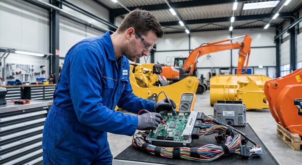
Hitachi excavators—from the classic EX200 series to modern ZAXIS ZX200, ZX210, and ZX330 models—rely on central electronic controllers to balance engine output with hydraulic demand. When an excavator’s computer board malfunctions, the machine can instantly lose power, lock up hydraulic functions, display communication alarms, or refuse to crank altogether.
For independent heavy equipment repair shop owners and fleet mechanics, electronic failures present a double-edged sword. Diagnosing a controller failure incorrectly leads to unnecessary replacement costs, whereas misdiagnosing a damaged wiring harness as a good board can ruin a newly installed controller in seconds.
This technical guide outlines the architecture of Hitachi excavator controllers, breaks down essential diagnostic trouble codes (DTCs), provides an ordered 5-step troubleshooting sequence, and details preventive maintenance practices to eliminate controller burnouts.
Architecture of Hitachi Excavator Electronic Control Systems
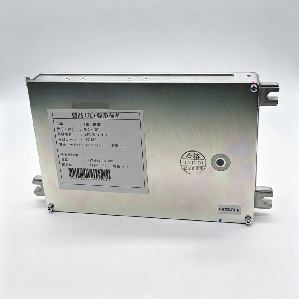
Modern Hitachi excavators utilize a dual-controller framework to separate hydraulic power management from engine fueling and emissions control:
- Main Controller (MC): Acts as the primary hydraulic coordinator. The MC receives inputs from the engine speed dial, pressure sensors, and pilot control switches. It regulates the hydraulic pump displacement solenoids, swing brakes, and travel speed valves.
- Engine Control Module (ECM / DCU): Coordinates electronic fuel injection, common rail pressure, and turbocharger boost levels (typically paired with Isuzu 4HK1, 6HK1, or 6WG1 engines).
- Monitor Controller: Processes machine operational data, liquid crystal display functions, and active fault logging via Controller Area Network (CAN bus) communication lines.
Engine Dial & Sensors → Main Controller (MC) → Pump Solenoids & Valves
(CAN-0 Bus)
Isuzu Engine Sensors → Engine ECM / DCU → Common Rail Injectors
(CAN-1 Bus)
Monitor Unit
When a breakdown occurs, determining whether the fault lies in the Main Controller, the Engine ECM, the connecting harness, or external sensor inputs is the first critical milestone.
5 Common Symptoms of a Malfunctioning Hitachi Computer Board
Before connecting diagnostic tooling, observing specific machine behaviors helps narrow down the failure mechanism:
1. Engine Will Not Crank or Dies Immediately
If the key switch is turned to the start position and the engine fails to crank while displaying a blank or frozen display monitor, the Main Controller or Engine ECM is likely experiencing an interruption in 24V DC power, a blown main controller fuse, or an internal micro-processor lockup.
2. Severe Hydraulic Speed Derate (“Turtle Mode”)
When the excavator operates in extreme slow-motion across all functions—boom, arm, bucket, swing, and tracks—the Main Controller has typically entered a safety limp-home mode. This usually stems from an internal pump driver failure or loss of CAN bus communication between the MC and engine controller.
3. Erratic Engine RPM or Loss of Throttle Control
If turning the engine speed control dial produces no response, or if engine speed hunting occurs under load, the signal voltage to the controller is compromised, or the controller’s internal analog-to-digital (A/D) converter circuit has degraded.
4. Persistent CAN Communication Alarms
Monitor alerts indicating CAN0 or CAN1 communication timeouts (such as code 11007-2 or 11009-2) point to a severed network line, a corrupted controller network transceiver chip, or improper terminating resistance across the network.
5. Burning Odor or Physical Board Discoloration
A distinct electrical burning smell coming from the cab storage compartment behind the seat indicates a shorted output driver transistor, usually caused by an externally shorted proportional solenoid coil or reverse-polarity battery jump-starting.
⚠️ Warning: Never jump-start a 24V Hitachi excavator using a 48V fast-charger or high-amperage boost charger without disconnecting the main computer board harness plugs first. Voltage spikes exceeding 32V DC will instantly rupture the controller’s internal transient voltage suppression (TVS) diodes and ceramic capacitors.
Key Hitachi Excavator ECU Fault Codes Demystified
Interpreting diagnostic fault codes correctly saves hours of shop labor. The following cross-reference table highlights common fault codes found across Hitachi ZAXIS (ZX-3 / ZX-5 / ZX-6) and EX series excavators:
| Fault Code | Affected Subsystem | Root Cause & Operational Symptom | First Diagnostic Action |
|---|---|---|---|
| 11006-2 | Engine Controller Harness | Loss of speed signal or harness break between MC and ECM. Machine hydraulics operate in slow mode. | Inspect harness continuity between MC connector and ECM pin rail. |
| 11007-2 | MC / CAN0 Network | CAN bus communication timeout at Main Controller. Hydraulic functions slow; monitor displays alert. | Measure CAN-H to CAN-L resistance (standard: 60Ω across parallel network). |
| 11009-2 | Monitor Controller | Communication fault between monitor unit and Main Controller. Screen freezes or misses operational vitals. | Check monitor supply voltage (24V) and monitor connector ground resistance. |
| 10514-12 (P060B) | Engine DCU / ECM | Internal DCU hardware failure or EEPROM checksum error. Engine fails to start or shuts down. | Verify main DCU ground; if voltage is clean, controller replacement is required. |
| E₀₉ / E₁₂ | MC Internal Logic | Internal memory (EEPROM) corruption (E₀₉) or CPU processing fault (E₁₂). | Reset controller power rail. If code persists, internal board bench repair or swap needed. |
| 11101-3 / 11101-4 | Speed Dial Sensor | Engine speed dial signal voltage abnormally high (shorted to 24V) or low (shorted to ground). | Test throttle knob potentiometer signal wire (normal range: 0.5V to 4.5V DC). |
| 11200-3 / 11200-4 | Hydraulic Pump Sensor | Pump A delivery pressure sensor signal out of specified voltage bounds. | Test pressure sensor connector with multimeter; verify 5V reference supply. |
As noted in Volvo CE’s 5-step machinery diagnostic protocol, structured diagnostic workflows prevent mechanics from replacing functional components based on single error code readouts.
Systematic 5-Step Diagnostic Protocol for Hitachi Computer Boards
To execute a professional Hitachi excavator computer board troubleshooting sequence, follow this 5-step shop protocol:
Step 1: Physical Inspection → Step 2: Power & Ground Testing
Step 4: CAN Bus Resistance < Step 3: 5V Reference Check → Step 5: Module Isolation & Bench Test
Step 1: Visual and Physical Harness Inspection
Begin by opening the controller bay behind the operator seat.
- Inspect the wiring harness plugs for loose locking tabs, backed-out terminal pins, or green copper oxide corrosion.
- Check for oil or water ingress inside the multipin aluminum connector shell.
- Inspect external harness routing along the boom frame and hydraulic pump bay for chafing or pinch points. If external wiring is damaged, replacing it with an exact fitment Hitachi ZAX200 / ZAX230 / ZAX270 hydraulic pump wiring harness ensures clean signal delivery before re-testing the controller.
Step 2: Battery Supply Voltage and Ground Resistance Verification
Before condemning an electronic board, confirm that clean power reaches the unit under load:
- Set a digital multimeter to DC volts and probe the main 24V supply pins at the controller harness connector with the key switch ON.
- The supply voltage must match battery terminal voltage (typically 24.5V to 27.8V DC).
- Switch multimeter to resistance (Ω) and measure from the controller ground pins to the main machine chassis frame. Ground resistance must measure below 0.5Ω. A floating ground causes erratic voltage spikes that mimic internal board failure.
Step 3: Sensor Input and 5V Reference Supply Checks
Hitachi controllers generate a regulated 5.0V DC reference output to power external sensors (such as pump delivery pressure sensors and engine speed dials):
- Probe the 5V reference pin at the pressure sensor harness.
- If the voltage reads 0V or drops below 4.5V, disconnect external sensors one by one. If 5.0V returns when a specific sensor is unplugged, that sensor has an internal short circuit pulling down the controller’s internal voltage regulator rail.
- If 5V remains absent with all sensors unplugged, the internal 5V regulator chip on the computer board is damaged.
Step 4: CAN Bus Network Resistance Testing
Communication faults are frequently caused by wiring anomalies rather than damaged microprocessors. According to Fairtrade Machinery’s CAN bus diagnostic procedures, testing network termination resistance is the standard method for verifying datalink integrity:
- Turn off key switch and disconnect battery ground switch.
- Measure resistance between CAN-High and CAN-Low terminal pins at the diagnostic port or controller connector.
- Standard Value: The resistance across a healthy parallel CAN network equipped with two 120Ω terminating resistors is exactly 60Ω (tolerance: 58Ω–62Ω).
- Diagnostic Rules:
- Reading 120Ω: One terminating resistor or wire line is open/broken.
- Reading 0Ω or near 0Ω: CAN-H and CAN-L wires are shorted together.
- Reading Infinite (OL): Complete network open circuit.
Step 5: Module Isolation and Bench Testing
If power supply, grounds, sensor 5V reference rails, and CAN bus lines pass all multimeter tests, but the machine still displays persistent internal CPU/EEPROM errors (such as 10514-12, E₀₉, or E₁₂), isolate the board for bench testing or board-level replacement.
As detailed in Sinocmp’s guide to excavator controller working principles, bench testing involves supplying 24V DC to power pins and using an oscilloscope or logic probe to monitor crystal oscillator pulses and microprocessor output drivers.
Pro Tip: Always record and clear active fault codes after performing harness or sensor repairs. Disconnect the main battery ground switch for 3 minutes to cycle controller memory, then re-key the machine to confirm whether fault codes return immediately or only under hydraulic load.
Bench Repair vs. Board Replacement: Decision Framework for Shops
When a Hitachi computer board is confirmed faulty, repair shop managers face a choice between component-level bench repair and total board replacement:
Confirmed ECU Fault
Minor Trace / Driver Failure
- Blown MOSFET driver
- Corroded pin solder joint
- Replaceable relay/diode ( Bench Repair Feasible )
Processor / EEPROM Burn
- CPU cracked or shorted
- Multi-layer PCB burnt
- Corrupted main program ( Full Board Replacement )
When Component-Level Bench Repair Works
Bench soldering and component replacement are viable when damage is localized to peripheral output circuits:
- Shorted Solenoid Driver MOSFETs: Replacing blown switching transistors responsible for pump solenoid control.
- Cracked Cold Solder Joints: Reflowing cracked pin solder connections caused by engine vibration.
- Ruptured Protection Diodes: Replacing blown TVS diodes on the 24V input line after an accidental reverse-polarity boost start.
When Full Board Replacement is Required
Attempting bench repair is unviable under the following conditions:
- Microprocessor or EEPROM Internal Failure: CPU core short circuit or destroyed memory silicon.
- Charred Multi-Layer Printed Circuit Board (PCB): Carbonized board material creates conductive paths between internal copper layers that cannot be isolated.
- Extensive Water Damage: Deep corrosion destroying micro-vias across the circuit board.
As emphasized in YNF Machinery’s complete guide to excavator ECU repair, replacing a severely damaged board with a pre-programmed plug-and-play module is significantly more cost-effective for commercial repair shops than spending days chasing intermittent micro-fractures on an old PCB.
Preventive Maintenance to Extend Hitachi Controller Lifespan
Protecting delicate electronic controllers from harsh jobsite conditions is essential for preventing premature failure. Implement these shop maintenance standards:
1. Maintain Clean Ground Connections and Battery Terminals
Loose battery cables create high-voltage inductive kickbacks every time the alternator operates. Inspect and clean main chassis grounds every 500 operating hours to prevent floating ground spikes.
2. Enforce Proper Welding Safeguards
Before performing arc welding on an excavator frame:
- Turn off the main battery disconnect switch.
- Unplug all harness connectors from the Main Controller, Engine ECM, and Monitor Unit.
- Attach the welding ground clamp as close to the weld joint as possible—never clamp across a pivot bearing or electronic enclosure.
3. Ensure Watertight Enclosure Sealing
Verify that cab rubber weather-stripping and controller compartment covers remain tightly sealed. Dust and condensation build-up inside the controller case creates tracking paths that cause short circuits across high-density SMD components.
4. Replace Aged Wiring Harnesses
Vibration, hydraulic oil exposure, and heat cycles embrittle wire insulation over time. Adhering to a comprehensive excavator replacement parts maintenance guide helps technicians identify hardening harnesses and replace them before short circuits destroy sensitive controller electronics.
Sourcing Factory-Direct Hitachi Replacement Computer Boards
When a replacement controller is necessary, independent repair shops require exact model matching, pre-flashed software compatibility, and fast delivery to minimize equipment downtime.
Machine Serial & Engine Model
Hongtengda Technical Matching Pre-Programmed Plug & Play ECU → Zero-Downtime Installation
As a specialized manufacturer and distributor of heavy equipment components since 2001, Hongtengda Parts supplies factory-direct replacement computer boards and electrical components engineered specifically for Hitachi excavators:
- Pre-Programmed Plug-and-Play Units: Replacement ECUs and Main Controllers are flashed with exact OEM firmware calibrated for specific engine configurations (such as Isuzu 4HK1, 6HK1, or 6BG1 engine series).
- Exact OE Part Number Matching: Comprehensive coverage for Hitachi models including ZAX170W-3 (SCM Board #9274929), ZX200-3, ZX230, ZX270, ZX330-3, ZX350-5G (Main Controller #YA60001380), and EX200-2/3/5 series.
- Factory-Grade Quality Assurance: Manufactured with heavy-duty aluminum enclosures, vibration-damped circuit boards, and high-temperature connector pins rated for extreme construction environments.
- One-Stop Electrical Sourcing: From computer boards and monitor display panels to complete engine and hydraulic pump wiring harnesses, repair facilities can source complete electrical systems directly from the manufacturing source.
Repair shop leads and procurement managers can explore Hongtengda’s comprehensive Hitachi excavator parts catalog to locate compatible computer boards, or review the independent repair shop guide to sourcing Hitachi components for detailed cross-referencing and technical fitment support.
Summary for Independent Repair Facilities
Mastering Hitachi excavator computer board troubleshooting requires a structured diagnostic mindset:
- Never assume the board is dead first: Always verify 24V DC battery power under load, chassis ground resistance (<0.5Ω), and 5V sensor reference rails.
- Use CAN bus measurements: Validate the 60Ω network resistance across CAN-H and CAN-L to rule out harness opens before condemning communication hardware.
- Prevent repeat failures: Inspect solenoids and wiring for short circuits before plugging in a new replacement board.
- Partner with reliable factory suppliers: Utilize pre-programmed, plug-and-play computer boards to ensure rapid machine turnaround and protect shop repair profitability.
For immediate technical support or to verify OE part numbers for Hitachi computer boards, contact the engineering specialists at Hongtengda Parts.